| Wiring Diagrams by Jerome A. Lepinski for HO Scale Slot Systems |
H.O. Scale Slot Track Custom Wiring Diagrams from
|


|
|
|
Look through the list of wiring diagram descriptions below to see if you can
find the diagram you need to wire your layout.
Since the mid-seventies all slot car sets were produced with plug in
controllers and transformers, wiring diagrams are not provided for plug in style terminal tracks.
|
|
This system is used for AC Half-Wave Compliant vehicles only (Aurora Vibrators, and Diode Isolated Chassis designs).
If DC vehicles are powered by AC they will shake until they smoke.
If DC power is used with this terminal track section the vehicles will travel as opposing traffic.
|

|
|
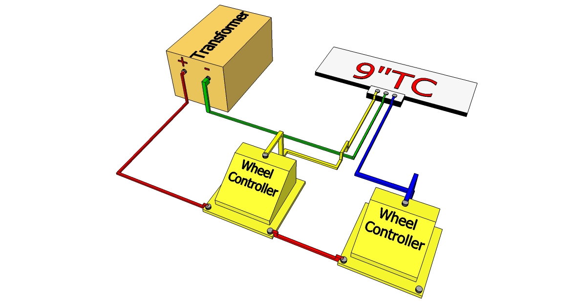
This is the most popular control system for DC powered vehicle.
This is a Common Ground wiring system so reversing controllers are not allowed.
It is also limiting, because if your transformer does not have enough amperage one vehicle will take
more of the power and if either car stops suddenly or de-slots the other car will get a boost of power.
|
|
|
|
This is an upgrade to the above system.
This is a Common Ground wiring system so reversing controllers are not allowed.
With two matching transformers and no common ground terminal tracks you will no longer have the problem mentioned above.
|
|
|
|
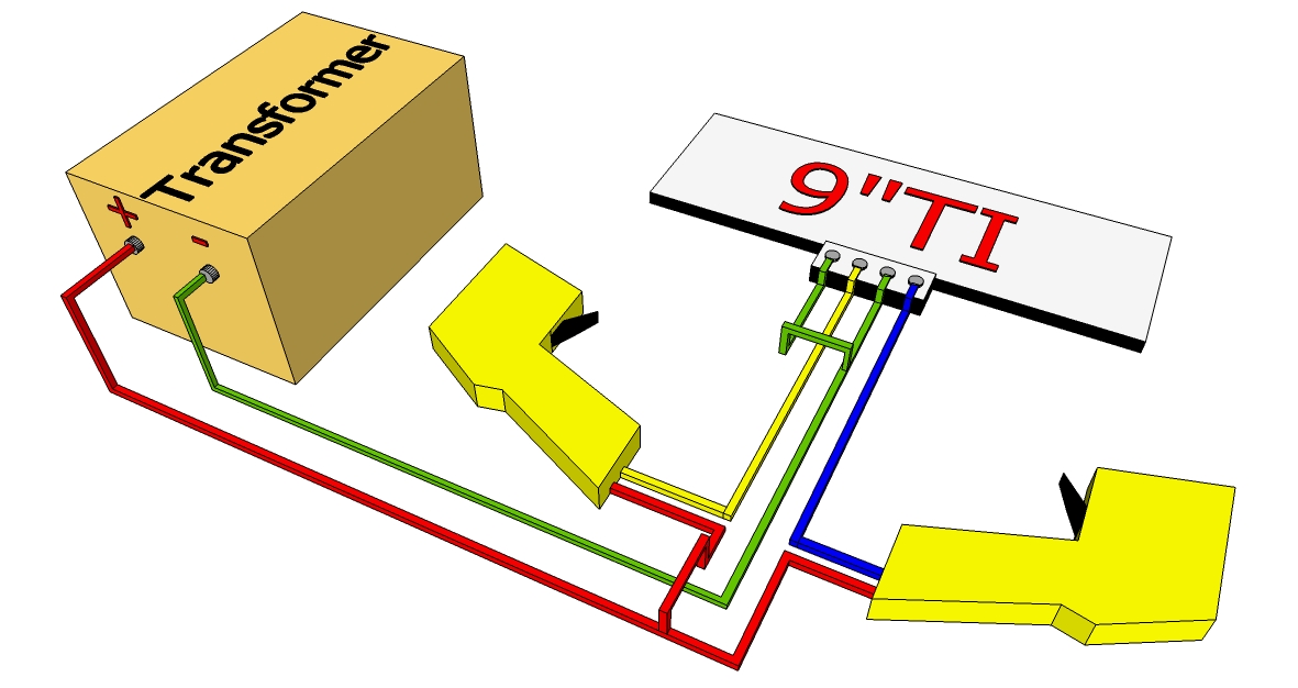
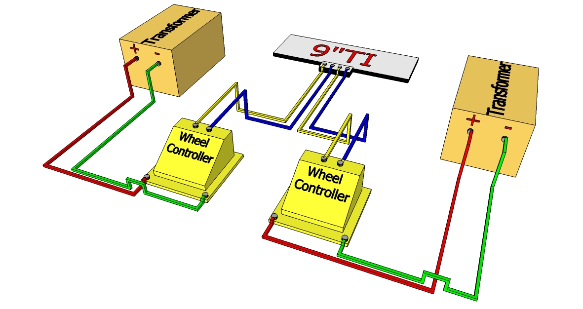
This is the second most popular control system for DC powered vehicles.
This is an Isolated Ground System so reversing controllers can be used.
It is also limiting, because if your transformer does not have enough amperage one vehicle will take
more of the power and if either car stops suddenly or de-slots the other car will get a boost of power.
|
|
|
|
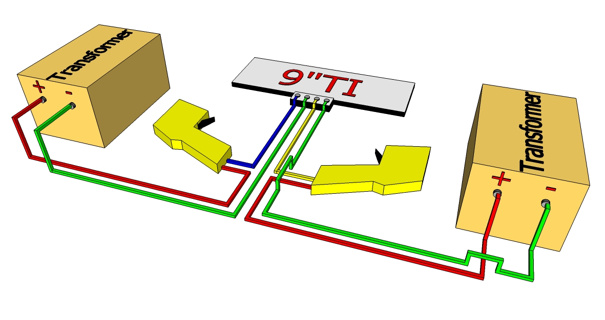
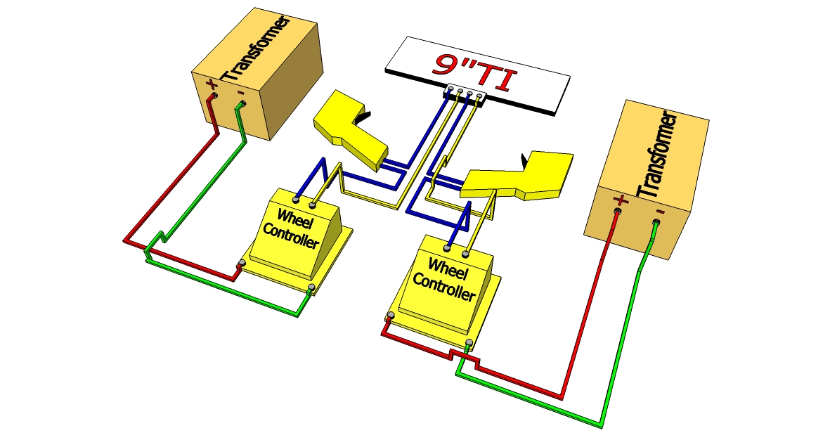
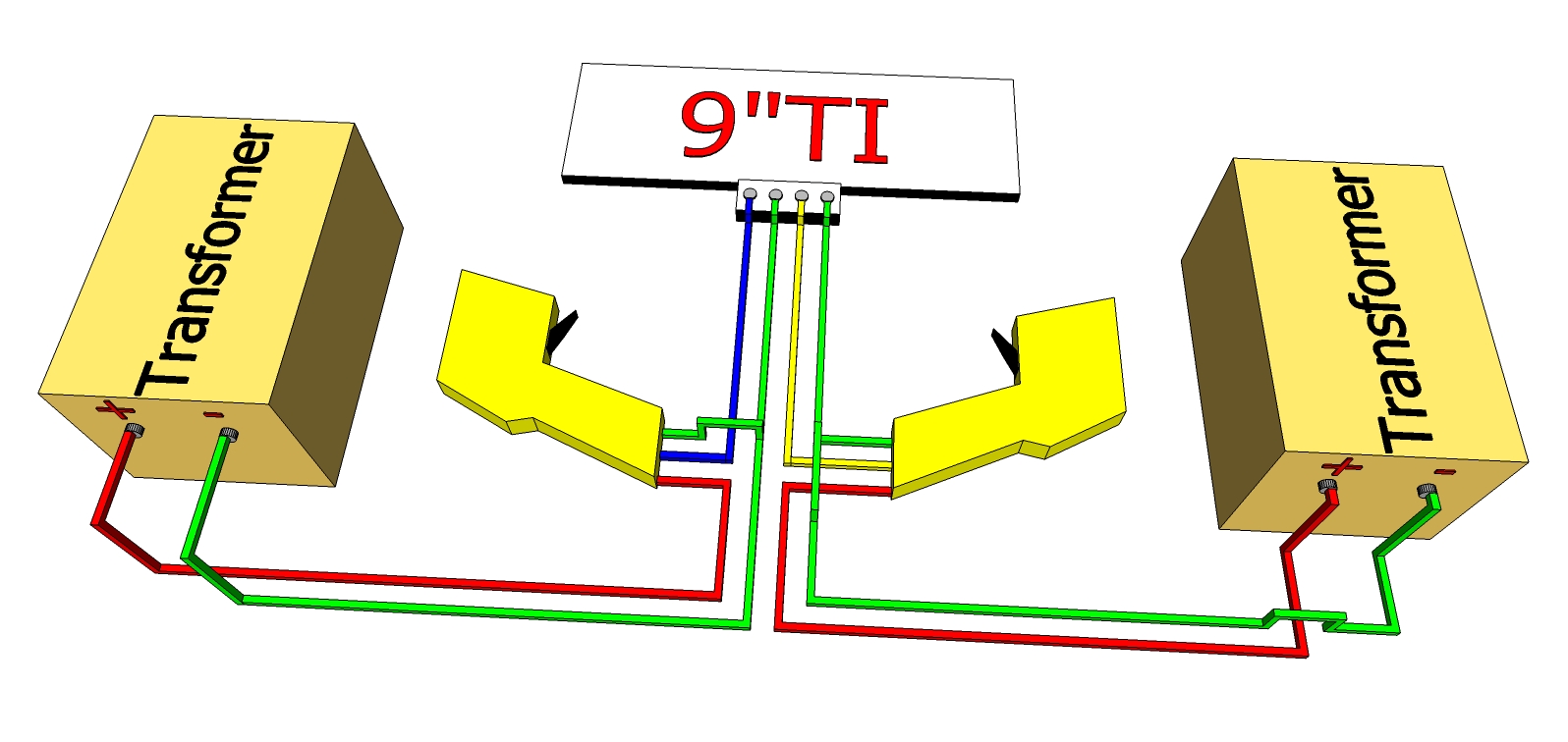
This is an upgrade to the above system.
This is an Isolated Ground System so reversing controllers can be used.
With two matching transformers and no common ground terminal tracks you will no longer have the problem mentioned above.
|
|
|
|
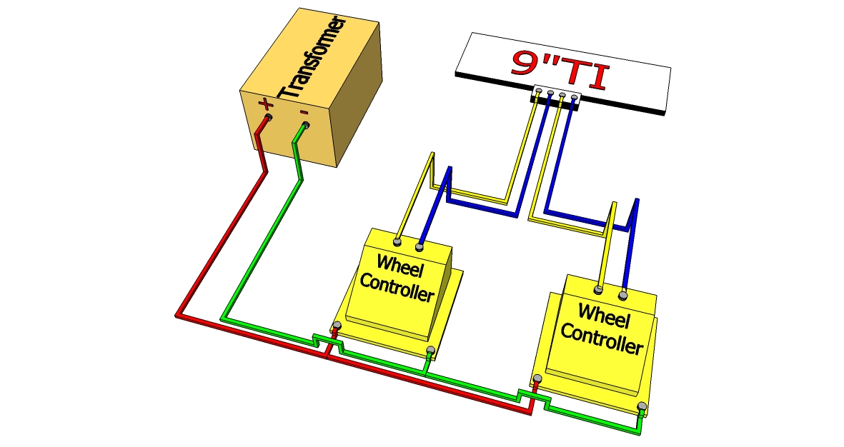
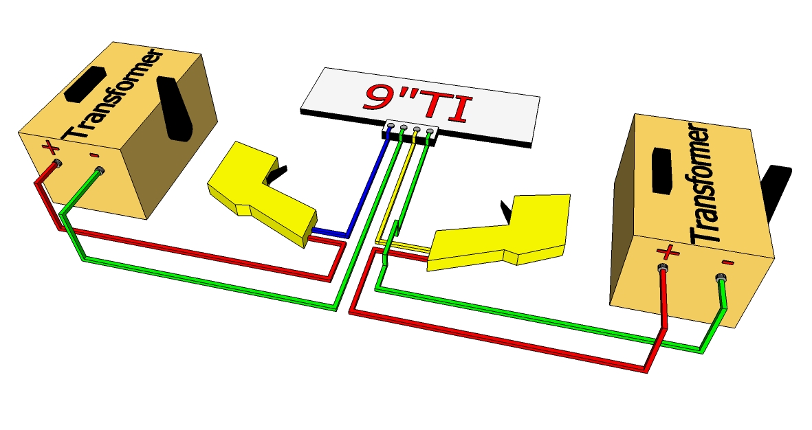
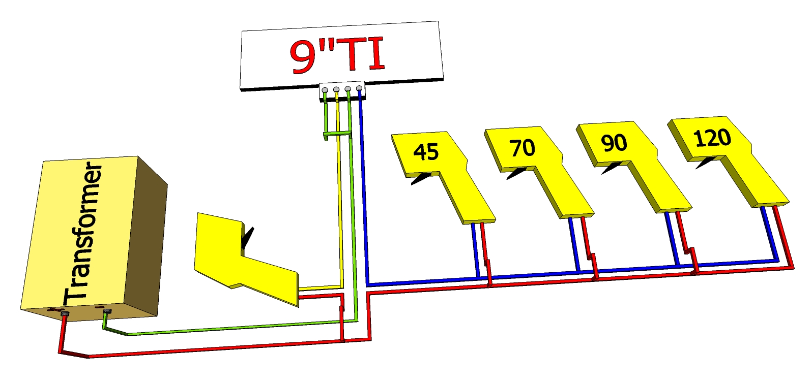
This is a high bred system which allows a governor for each lane.
Great for training children and novices on how to drive your layout.
Also helps new drivers learn the layout with fewer crashes.
|
|
|
|
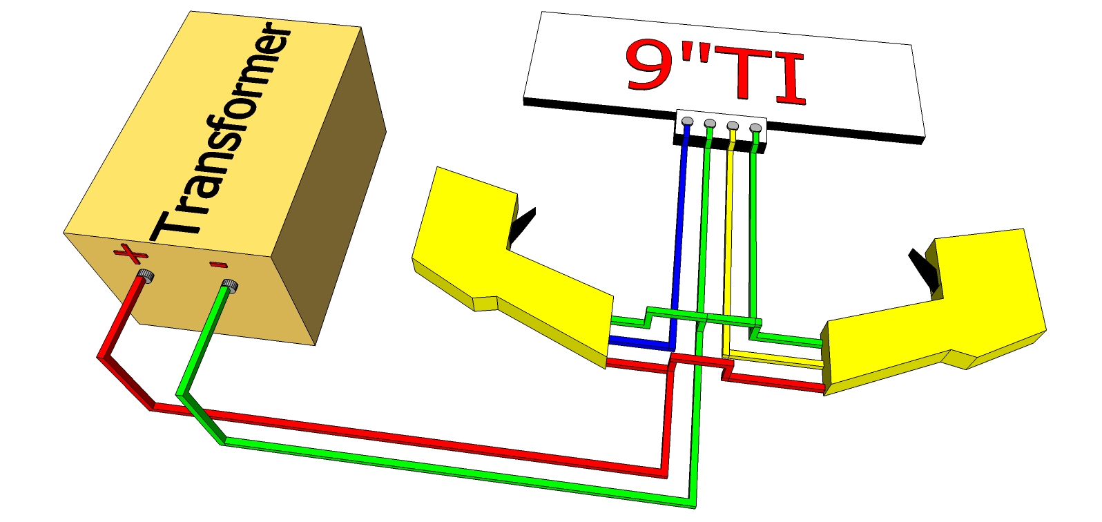
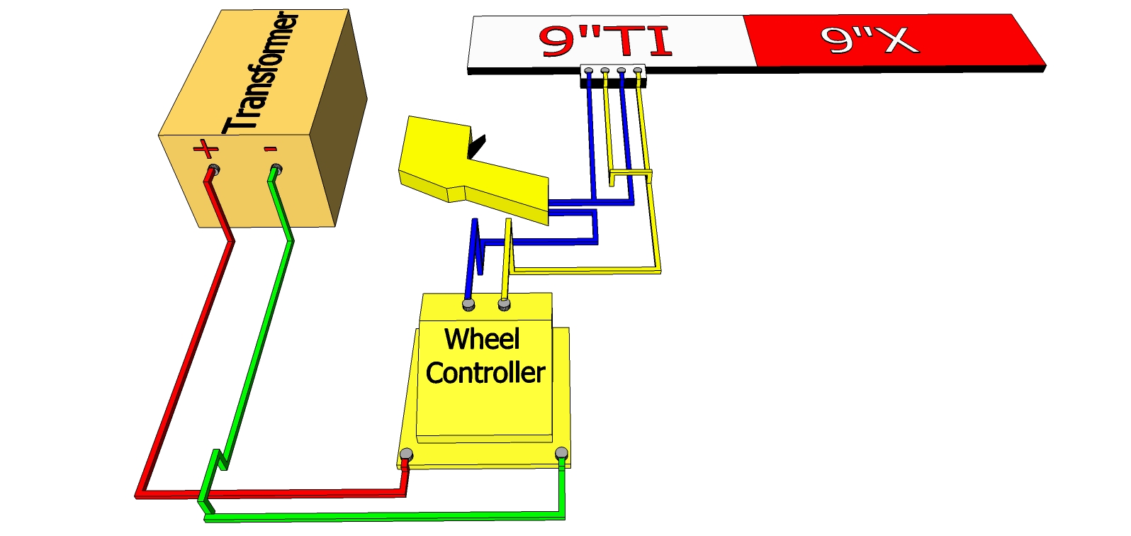
Using train transformers (variable Power) is another way to govern the lanes for training.
Problem with this system is most train transformers are below 14 volts.
|
|
|
|
This is a Common Ground system with brakes.
It is also limiting, because if your transformer does not have enough amperage one vehicle will take
more of the power and if either car stops suddenly or de-slots the other car will get a boost of power.
|
|
|
|
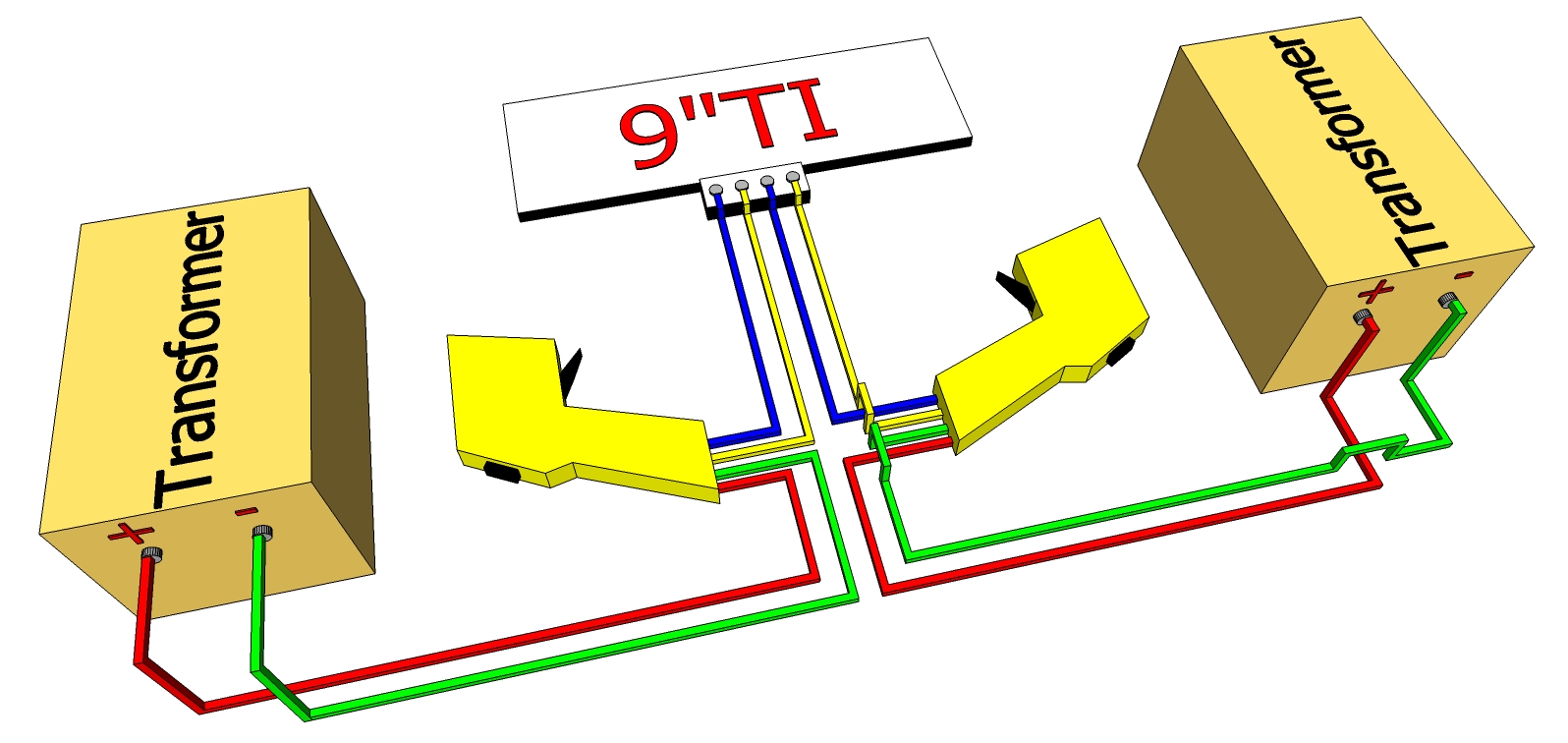
This is a Dual Transformer Isolated Ground system with brakes.
With two matching transformers and no common ground terminal tracks you will no longer have the problem mentioned above.
|
|
|
|
This is for reversing controllers and must be wired as Isolated Ground for it to work properly.
|
|
|
|
This is a governed trigger set up to run a two lap layout.
By using a single or odd number of Lane Change track section in a Layout you can use both lanes on a single lap.
|
|
|
|
This image is to show that numerous controllers can be wired into the layout at the same time.
With this method whichever controller you pick up will control the lane and the rest will have no affect unless another trigger is pulled.
|
|
|
_____Adding Additional Terminal tracks, Power taps, or Jumpers_____
|
|
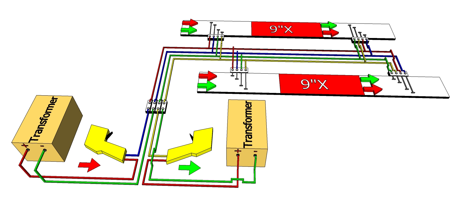
It is much easier to add a terminal block between the power supply and multiple terminal tracks.
Shown are the four ways that two cars can pass through a terminal track in your layout.
If you are not using the terminal track screws or plugs notice the rail indicators on the track sections.
Use anyone of the wiring diagrams at the top of this page, but wire to a terminal block instead of the terminal track.
All tracks or power taps should be connected from the top of the terminal block.
For clarity the wire colors change at the terminal block.
The color of the wire does not matter only that the ends are connected correctly.
Problems may result from using common ground terminal tracks.
Be sure to cut all common ground straps, even the on-powered ones impersonating straight track.
|
|
|
_____Testing Connectivity_____
|
|
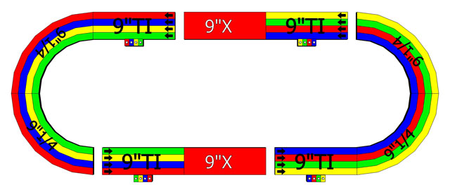
Notice the gaps in the layout are for testing in a Counter Clockwise direction.
Also notice how the terminal tracks are all in the same direction but the screw colors are not the same pattern.
One of the above wiring diagrams should be used to connect the first terminal track.
All additional or secondary terminal tracks or power taps should be connected from the wires connecting to the primary terminal track.
Problems may result from using common ground terminal tracks.
Be sure to cut all common ground straps, even the ones impersonating a straight track.
To make additional terminal tracks less obtrusive in the layout,
consider cutting the screw or plug block and all of the straps (leaving enough room for a 1/4" Electrical Spade Terminal to be slipped onto the stub of the straps).
|
|
|
_____Cheap Power Hack_____
|
|
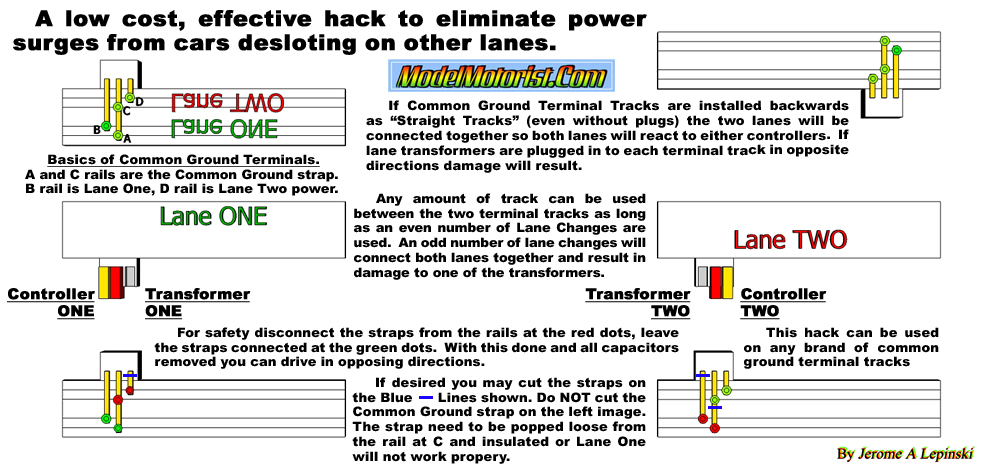
Using this method you can have drivers at either end of the layout or either side.
You can run different voltages in each lane without transformer failure.
This is good for training visitors or help the young keep the cars on the track.
Once this is done you can run traffic in opposing directions without transformer failure.
This system should be tested with the terminal tracks disconnected from the layout.
It is too easy to think a terminal track can be a straight track, but it can cause problems.
The common ground strap used in the terminal tracks will allow bleeding of power between the two transformers (In-Line).
The common ground strap will connect the two control rails together so both controllers will control both lanes (Backwards)
Capacitors should be removed before using opposing traffic flow.
|
|
|